Decoder Circuit Diagram And Truth Table [diagram] 1 Of 8 Dec
Decoder encoder edupointbd Understanding decoder truth tables and circuit diagrams [diagram] circuit diagram from truth table
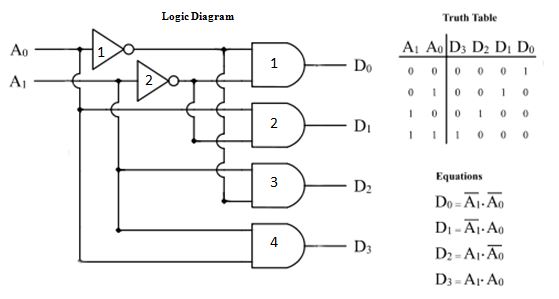
Decoder Circuit Diagram And Truth Table
Truth tables calculator – two birds home Decoder truth table binary diagram computational optimization method based math ece engineeringstudents tables [diagram] 1 of 8 decoder logic diagram
Decoder, 3 to 8 decoder block diagram, truth table, and logic diagram
Decoder electronics digital circuit javatpoint encoders topic nextBinary #decoder truth table #ece #engineeringstudents The 2-bit decoder (a) block diagram (b) truth table for active-l o/psTruth table of decoder.
4 to 16 decoder using 2 to 4 decoder verilog code[diagram] relay logic diagram 3 to 8 decoder circuit diagram. 3 to 8 decoder truth table.16 to 4 encoder truth table.
![[DIAGRAM] 1 Of 8 Decoder Logic Diagram - MYDIAGRAM.ONLINE](https://i.ytimg.com/vi/3per0Uq3BnA/maxresdefault.jpg)
Decoder in digital electronics
[diagram] 1 of 8 decoder logic diagram[diagram] logic diagram of bcd to decimal decoder Instrumentation in a nutshell: decoderDigital and computer system [2].
3-to-8 line decoder.3 to 8 decoder Codeur en logique numérique – stacklima[diagram] 2 4 decoder logic diagram.
![[DIAGRAM] Relay Logic Diagram - MYDIAGRAM.ONLINE](https://i2.wp.com/www.electroniclinic.com/wp-content/uploads/2020/05/3-to-8-line-decoder-logic-diagram.png?fit=6700%2C5719u0026ssl=1)
Encoder truth table and circuit diagram
Decoder circuit diagram and truth tableEncoder logic circuit binary electronics encoders circuits combinational tutorial combination care shows figure don unit Decoder circuit diagram using gatesBinary decoders: basics, working, truth tables & circuit diagrams.
Decoder logic circuit diagram and operationDecoder diagram block truth table logic Encoder and decoder circuits[diagram] 2 4 decoder logic diagram.

Decoder circuit with truth table
Understanding decoder truth tables and circuit diagrams8 to 3 priority encoder circuit diagram Decoder truth table active output eight three not watson inputs multiple create just here descriptionDecoder circuit diagram using gates.
Decoder logic rangkaian output equations instrumentation decodificador input vlsi nutshell demultiplexer combinational verilog circuitos inputs encoder bcd ingressi integrato codingDecoder circuit binary diagram basic truth decoders logic circuitdigest gate block tables using basics working not saved following draw .

![[DIAGRAM] 1 Of 8 Decoder Logic Diagram - MYDIAGRAM.ONLINE](https://i2.wp.com/www.elprocus.com/wp-content/uploads/4-to-16-decoder-circuit.bmp)
[DIAGRAM] 1 Of 8 Decoder Logic Diagram - MYDIAGRAM.ONLINE

Decoder, 3 to 8 Decoder Block Diagram, Truth Table, and Logic Diagram

Understanding Decoder Truth Tables and Circuit Diagrams

Codeur en Logique Numérique – StackLima

Encoder and Decoder Circuits - HSC
![Digital and Computer System [2] - Combinational and Sequential Systems](https://i2.wp.com/www.elprocus.com/wp-content/uploads/2-to-4-Decoder-Circuit-1.jpg)
Digital and Computer System [2] - Combinational and Sequential Systems

Decoder Circuit Diagram And Truth Table
INSTRUMENTATION IN A NUTSHELL: DECODER